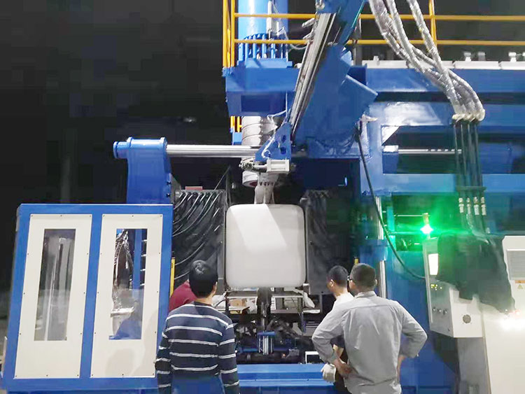
The IBC (Intermediate Bulk Container) TANK is a popular choice for storing and transporting liquids and powders. In this article, we'll introduce the equipment parts of the IBC tank blow molding machine and their importance in the manufacturing process.
IBC tank blow molding machines include mechanical, electrical, hydraulic, air, water and other parts.Understanding the functions and capabilities of each component is essential to ensure that the IBC tank blow molding machine operates efficiently and effectively.

Mechanical part
The mechanical part includes: extrusion system; accumulator die head; clamping system; lifting device; blowing device; robot arm, etc.
Extrusion device
The extrusion device is the key part of the extrusion blow molding machine. The extrusion device is used to plasticize the plastic raw materials. Its main functions are:
(1) Conveying solid raw materials, feeding plastic from the hopper into the screw.
(2) Molten plastic, melt the plastic which is feed into the machine screw.
(3) Mixing, conveying the melt, feeding the plasticized plastic into the die, and then forming a parison through the die.
The extrusion device of this machine is mainly composed of motor (110KW), AC speed controller, gear reducer (two-stage transmission), barrel and screw, heater, cooling fan and so on. The working process of the extrusion device is:
 the twisted material motor is decelerated by the gear reducer, and the increased torque is transmitted to the screw; under the action of the rotating screw, through the friction between the inner wall of the barrel and the surface of the screw, the The plastic entering the screw is conveyed and compacted forward; when the plastic enters the compression section from the feeding section, as the plastic continues to be conveyed forward, and due to the gradual shallowing of the screw groove and the obstruction of the die, the plastic is gradually formed At the same time, the material is subjected to the external heating from the barrel and the strong stirring, mixing and the twisted material motor is decelerated by the gear reducer, and the increased torque is transmitted to the screw; under the action of the rotating screw, through the friction between the inner wall of the barrel and the surface of the screw, the The plastic entering the screw is conveyed and compacted forward; when the plastic enters the compression section from the feeding section, as the plastic continues to be conveyed forward, and due to the gradual shallowing of the screw groove and the obstruction of the die, the plastic is gradually formed At the same time, the material is subjected to the external heating from the barrel and the strong stirring, mixing and shearing of the screw and the barrel, and the plastic is gradually melted. At the end of the compression section, the plastic is completely or largely Part of it is melted and transformed into a viscous flow state; after entering the metering section, due to the action of the mixing head at the end of the metering section, the viscous flow plastic is further plasticized and homogenized, so that it can be extruded at a constant pressure, quantity and temperature. into the die head.

The gear reducer adopts a high-precision hard tooth surface gear reducer specially used for plastic machines. The gear material of the gear reducer is made of high-quality low-carbon alloy steel, which is processed by carburizing, quenching and gear grinding. The hollow output shaft of the gear reducer adopts a thrust self-aligning roller bearing with high load capacity to withstand the huge recoil force of the screw working. The hard tooth surface gear reducer has the characteristics of small size, high load capacity, stable operation, low noise and long life. After the reducer is first used for one month, it needs to change the lubricating oil and clean the oil filter, and then replace it every 1500-3000h, and the interval between each replacement should not exceed 18 months. Fill the gearbox with lubricating oil, and add medium extreme pressure industrial gear oil N220 to the upper limit of the oil standard.
The adjustment cylinder is a functional small part for installing the mold. Start the function of moving the die head forward and backward, and the whole extrusion device and the die head will move forward or backward.
Die head
The extrusion blow molding machine adopts accumulator die head, the material storage chamber is set in the flow channel of the die head, and the extrusion device directly feeds the die head, which can basically guarantee the "first in first out" of the melt, that is, when the injection piston is emptied downwards When the material storage cavity is injected, the melt that first enters the material storage cavity is first injected from the die. The die head adopts side feeding method. At the same time, the melt "first in, first out" shortens the time of refueling and color changing, and the operation is quick. The wall thickness control oil cylinder on the die head cooperates with the parison automatic control system to realize the automatic control of the axial wall thickness of the parison.
The melt extruded from the extruder enters the head through the joint neck of the head of the storage cylinder. The melt is continuously extruded from the extruder into the storage tank of the machine head, and the heating ring and the thermocouple keep the melt at a certain temperature, and the melt squeezed into the storage tank builds up pressure, pushing the injection The material piston, the injection material pillar, and the injection cylinder piston go upward slowly, and when the volume of the material storage cylinder reaches the set value, the material extrusion is stopped. After the injection is started, the wall thickness control system sends out a continuous signal, and the wall thickness control cylinder shifts the thickness adjustment rod, that is, the die has a certain amount of opening relative to the core die. At the same time, the injection cylinder injects material at a certain speed and pressure, and the melt flows out from the opening of the die to form a parison. The wall thickness of the parison is controlled by the electrical and hydraulic control system according to the curve set by the wall thickness control system.
Four adjusting screws are arranged in the circumferential direction close to the outlet of the die to adjust the radial wall thickness of the parison. By adjusting the position of the outer mold nozzle, the slight misalignment between the outer mold nozzle and the inner mold nozzle is eliminated, so that the radial wall thickness of the parison can be adjusted evenly, and the parison is guaranteed to be vertical and not bent.
The wall thickness adjustment nut on the die head is used to adjust the wall thickness of the parison. By turning the wall thickness adjustment nut, the thickness adjustment rod is driven to move axially, so that the inner die mouth produces axial displacement, changes the gap between the die openings, and achieves the purpose of adjusting the wall thickness of the parison. When we use the parison axial wall thickness automatic control system, the wall thickness adjustment nut is used for zero adjustment, that is, the zero position of the wall thickness control cylinder is adjusted to be consistent with the zero position of the die gap. For the specific operation method, see the parison shaft Instructions for the use and operation of the wall thickness automatic control system. When we use the parison automatic control system, the lock nut on the wall thickness control cylinder should be loosened so as not to affect the action of the wall thickness control cylinder.

Attention
1. When driving the injection material, the die head must be heated to the working temperature and kept warm for 3-4 hours. Otherwise, it will cause damage to the die head, especially the flow channel of the die head and the working surface of the injection piston. In severe cases, the main key will be scrapped.
2. The heating ring of the die head should be checked frequently to see if it is burnt or loose, and it should be replaced or tightened in time when found.
3. Start the machine again after shutting down, each section of the die head must be heated to the set temperature and kept warm for 3-4 hours before starting up, otherwise the heat inside the die head may damage the extruder and die head parts.
4. The overflow (usually black) in the overflow hole of the die head should be cleaned frequently to ensure the cleanliness of the die head and the product. The overflow on the die is not allowed to hang, and it should be cleaned once a week.
Clamping device
The ibc tank extrusion blow molding machine adopts single-cylinder rack and pinion synchronous centering mold clamping device. The front formwork and the pull arm are fixed by pull rods. The front and rear templates and pull arms are connected to the bed through linear guides.
When we design the mold, we need to determine the installation size of the mold according to the position of the mold installation hole on the template.

Machine frame
The IBC tank machine frame is mainly composed of safety doors, railings, lifting devices, ladders, machines and other parts. The machine table is supported by 4 screws. There is a worm gear lifting mechanism between the machine table and the mold clamping device. The low-speed high-torque hydraulic motor drives the sprocket rotating pair, which synchronously drives four sets of worm gear and screw pairs to drive the screws to realize the vertical linear motion of the machine table. Reach the die head lifting function.
Electrical part
The electrical part includes: PLC; AC speed control system; heating and temperature control system of die head and extrusion unit; wall thickness control system; related safety protection system, etc.
Hydraulic part
Host hydraulic system
The hydraulic system of IBC tank extrusion blow molding machine is mainly composed of power source, pressure regulating valve plate, reversing valve plate, injection valve plate, down blowing valve plate, etc. Lowering, advance and retreat of the die head, up and down of the blowing needle, opening and closing of the material, provide hydraulic energy and control.
Wall thickness control system
The wall thickness control system of IBC tank blow molding machine includes a parison wall thickness controller (Barber-colman), a hydraulic source, an electro-hydraulic servo valve, and a thickness cylinder. The parison wall thickness controller drives the thick and thin oil cylinder by controlling the opening degree of the electro-hydraulic servo valve with the pre-set parison thickness control value, and the action position of the thick and thin oil cylinder is fed back to the controller through the feedback potentiometer for comparison with the set value . The deviation signal between the set value and the feedback value controls the action of the electro-hydraulic servo valve to drive the thick and thin oil cylinder until the deviation signal is zero, thereby realizing the closed-loop control of the thick and thin oil cylinder, and indirectly controlling the wall of the accumulator die head to inject the parison. thickness control.
When the material in the die head reaches the set value and starts to shoot, the parison wall thickness controller receives the signal and controls the up and down movement of the thick and thin oil cylinder through the electro-hydraulic servo valve according to the preset curve, and the movement position of the thick and thin oil cylinder is The feedback potentiometer is fed back to the parison wall thickness controller to compare and track with the set signal, so that the actual motion curve of the thick and thin oil cylinder approaches the set curve, so as to achieve the purpose of controlling the wall thickness. The working curve of the parison wall thickness controller can be set arbitrarily.

Air system
The air system includes: the drive of the manipulator cylinder and the blow molding part of the product.
Waterway system
The waterway part includes: cooling circuits for molds and other parts.
The waterway system in an IBC tank blow molding machine is also important part responsible for maintaining the temperature of the molds during the blow molding process. It is a network of cooling circuits that are designed to regulate the temperature of various parts of the machine. This system is responsible for keeping the molds at a consistent temperature to ensure that the plastic material can be formed into the desired shape. It is crucial to have an efficient waterway system to avoid problems such as uneven cooling, shrinkage, and warping of the final product. The waterway system is a critical part of the IBC TANK blow molding machine that needs to be carefully designed and maintained to ensure optimal performance.
In summary, the IBC tank blow molding machine is a complex piece of equipment that consists of several critical components working together in harmony. The machine's extrusion system, die head, clamping system, parison control system, and waterway system all play important roles in producing high-quality IBC tanks. Understanding the function and importance of these components can help operators optimize the machine's performance, ensure product quality, and maximize production efficiency. With proper maintenance, training, and operation, the IBC tank blow molding machine can be a valuable investment for businesses looking to produce large-volume plastic containers.


